Detection Sensor
One
of the most noteworthy concepts to show up in
model
rocketry in many years. This article will show
you
how to build, test, and fly a Magnetic Apogee Sensor.
Written by Scott Aleckson
References:
Sport
Rocketry, Sep/Oct 1999, pp 6-9
Sport
Rocketry, Mar/Apr 2000, pg 18
To
get Sport Rocketry, join the NAR
Honeywell,
Inc.
Honeywell
Magnetic Sensor Products
Usenet:
rec.models.rockets
Free
web-based access at RemarQ
Original
Article by Robert Galejs
Archived
by
Essence's
Model Rocketry Reviews
This
concept was first introduced by Robert Galejs
in
Sport Rocketry Magazine. As it turned out,
there
were a couple errors in the published
schematics
and that design didn't work.
Since
I had the Honeywell HMC1001 chip in
my
possession, I began doing some breadboard
tests
and came up with a very simple circuit
that
performed flawlessly. Robert recently
updated
the original schematics to correct
the
previously published errors.
Get your HMC1001 from Newark Electronics.
Search for Newark part #91F4713 from their homepage.
The theory behind
the Magnetic Apogee Sensor is to use a small
magnetoresistive
(MR) microcircuit which contains a Wheatstone Bridge.
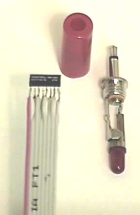
This tiny chip is
sensitive to changes in a magnetic field.
The Honeywell HMC1001
has only one axis of detection,
which runs from
the side with the pins toward the beveled top edge.
Changes in the orientation
of the magnetic field, or changes in the
HMC1001's position
within a magnetic field, will cause internal
changes in resistance.
By applying a supply voltage to the chip, we can
compare the two
output voltages. When the chip is aligned with a
magnetic field,
the outputs will be equal. When the chip is perpendicular
to a magnetic field
there will be a change in resistance, which will cause
an offset in the
outputs. This offset can be measured with an
Operational Amplifier,
such as a 741 Op Amp, and when these
offset voltages
change, the op amp will amplify the difference
between them.
Look at the diagram below.
When the HMC1001
is aligned with a magnetic field,
the outputs will
be equal and there will be no output
from the op amp.
A change in the magnetic field
orientation will
cause the outputs to change and a
signal will be
amplified by the op amp.
Now we need to make that signal useful.
By connecting that
output to a switching transistor,
known as a Field
Effect Transistor, we can use that "switch" to
activate an ejection
charge circuit to fire a flashbulb or match.
In this case we
are using an N-MOSFET, which means
an N-Channel Metal
Oxide Semiconductor Field Effect
Transistor.
Since that's a mouthful, we'll just call it a FET.
One of the best
qualities of a FET is that it has a very high
resistance in the
"off" state which isolates the Source and Drain
sides very much
like a mechanical switch. There is also
isolation between
the Gate side and the Source and Drain.
It only takes a
very small voltage at the Gate to allow
current to flow
between the Source and Drain on a FET.
Note that FETs are
very sensitive to static electricity
and should be handled
with great care.
The diagram below
shows how the FET is
connected to the
output of the op amp.
The presence of
a voltage at the Gate will allow current
to flow between
the Source and Drain pins on the FET.
With zero volts
at the Gate, the resistance between the
Source and Drain
is nearly infinite-- an excellent switch.
Calibrating the sensor.
As is, this circuit
may work correctly in some parts of the world.
The trick here,
is going to be calibrating your sensor to match the
area where you are
going to launch your rocket. The Earth is a big
magnet, and we are
going to use this sensor to detect the Earth's
magnetic field.
Think back to science class. Remember that
experiment where
you put iron powder on a piece of paper
and held a magnet
under it? A magnet has field lines that
start near the south
pole and end near the north pole.
Here is a simplified
diagram showing a typical magnetic field.
The Earth's
magnetic field is very similar. If you are near the
north or south magnetic
poles, the magnetic field lines would be
close to vertical.
If you are near the equator, then the lines would
be close to horizontal.
For the purposes of our sensor project,
the closer you are
to either of the poles, the more accurate
your sensor will
be. You should mount the sensor so that it's
sensing axis is
vertical to match the field lines.
A problem exists
for the areas in between. As you move from one
of the poles towards
the equator, the angle of the field lines to the
Earth's surface
will gradually fall from vertical towards horizontal.
In order to use
a magnetic reference in these areas, you would
have to mount the
sensor parallel with the field lines and have a
guidance mechanism
onboard the rocket to keep it rotationally
oriented in the
correct direction. This is beyond the scope of
model rockets, so
we'll just say that you shouldn't use this sensor
in those areas.
So, for everyone below the Mason-Dixon line,
sorry, but you'll
have to stick with timers and altimeters.
Finally, there will
be some differences between individual MR chips
as well as op amps
and other components in your circuit. For this reason
it is important
to calibrate every sensor before using it. To calibrate, we
are going to put
a resistor between the MR's positive output and ground.
We will adjust the
value of that resistor until the unit triggers our FET
at the appropriate
angles. It should trip near the horizontal position
when tilted to the
East or West. In the Northern Hemisphere, the sensor
will activate at
a higher angle to the North than to the South.
Try to calibrate
it to where it trips just above horizontal to the North
and just below horizontal
to the South. The Earth's magnetic
inclination angles
are somewhere around 70 degrees at
my location.
These are the results of my bench tests, with
positive angles
measured above horizontal and negative
angles measured
below horizontal:
Calibration resistor
values with bench test triggering
angles measured
referenced to horizontal.
Positive angles
are above horizontal and
negative angles
are below horizontal.