Detection Sensor
This schematic is a modification of the original
designs published by Robert Galejs in
Sport Rocketry magazine
Sport Rocketry, Sep/Oct 1999, pp 6-9
Sport Rocketry, Mar/Apr 2000, pg 18
Sport Rocketry can be obtained by joining the
National Association of Rocketry
His article can be read at
Essence's Model Rocketry Reviews
Click HERE for a direct link to that article
Honeywell Magnetic Sensors
The HMC1001 can be obtained from
Newark Electronics
Search for part #91F4713
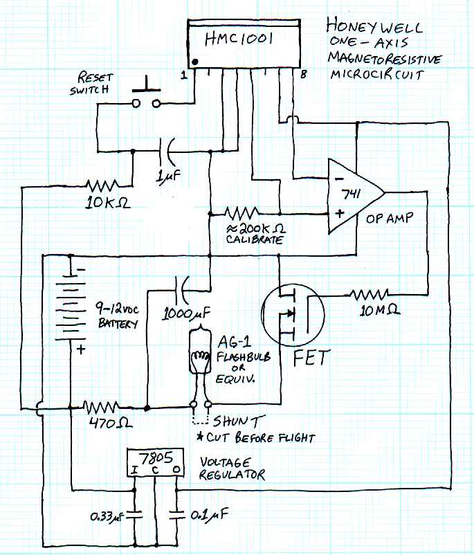
After reading Robert's article, I immediately wanted to build this project so I ordered an HMC 1001 sensor and started breadboarding the circuit. As it turns out, there were a couple errors in the schematic that appeared in Sport Rocketry. I took Robert's design apart and did a bit of redesigning to make it work. There has since been a correction published, but I had already come up with a much simpler circuit that works perfectly. Instead of trying to amplify then compare the outputs, I simply used a single op-amp as a comparator right off the magnetic sensor. Like the original, this drives a Field Effect Transisor to fire a flashbulb (or e-match) circuit.
I also found that the voltage regulator really isn't neccessary. The components are rated for up to 12 volts, so a 9 volt battery could be used to power everything without having the 5 volt power supply from the regulator. Be cautious as the HMC 1001 can be damaged if it sees more than 12 volts. According to Honeywell, the circuit performs better with a 5 volt supply, so I have left the regulator in this schematic.
Another option on the power supply is to use the 544 battery. This is a small 6 volt battery found in the photo section. The battery is a little smaller than an "N" cell and measures about 1/2" diameter and 1" long. They are also available in Lithium. I built a circuit without a voltage regulator using a single Energizer 544 battery. It was able to fire the smaller flashbulbs taken from flash cubes very well, but didn't have the power to handle the larger AG-1 flashbulbs. Of course it was easy to simply replace that battery with a standard 9 volt and it will fire the AG-1 bulbs just fine. I haven't done any testing with electric matches or any other type of ignitor.
For the serious weight conscious project and to guarantee that you have the power to fire your ejection charges, an idea I came up with here is to use two 544s in series. Two of these little batteries end to end are just about a perfect match to a single AA battery. The diameter is slightly less, but guess what? They fit perfectly inside a piece of 13mm body tube, which just happens to have the same outside diameter as an AA battery. So cut a 1 7/8" long piece of 13mm body tube, slide in two 544 batteries, and put it in a standard AA battery holder. You now have a 12 volt power supply that weighs about 1 ounce compared to over 1 1/2 ounces just for a single 9 volt battery. Not to mention the reduced size. Pretty sweet, eh? If you use this power supply, you have to use the voltage regulator circuit or you risk damage to the HMC chip.
Another noteworthy item that came up during bench testing was that when you first power up or even disconnect the circuit, there is a very brief surge of voltage that will go through the flashbulb. I was using an LED on the bench during my testing in place of the flashbulb, and it flashed every time you turn the power on or off. This is apparently a leak through while the capacitor is charging, or may be a quirk in either the op amp or the FET. Either way, it could cause the flashbulb to fire, so I added a shunt to the flashbulb (which you ought to do anyway, no matter what circuit you are using). This could either be a piece of wire that you cut just before leaving the rocket on the pad, or a jack with a shorted "remove before flight" plug. I set mine up with a jack and plug setup. Just make sure the plug is in place before connecting the flashbulb and before turning on or off the power. Although I put a power switch on mine (SPST slide switch at the positive battery terminal), you could just install or remove the battery to power it up if the battery will be readily accessable.
The push button switch in this circuit is the set/reset circuit for the magnetic sensor. If it is exposed to a strong magnetic field, the orientation of the sensor can be changed. The HMC circuit has a built in coil to apply a small correcting magnetic field. Before flight, you simply tap this switch to discharge the small capacitor through that coil and make sure the sensor is oriented properly. The sensor as wired in this circuit has to be mounted so that the beveled top edge is pointing toward the nose cone and the pins are pointing toward the motor. Do not put any ferris metals or magnetic sources near this circuit! It would be best to use plastic, brass, or stainless fasteners in the area where this circuit is mounted. You should also locate the battery pack as far away as possible. A stainless steel launch rod would be a good idea, too.
Final note here is on calibration. I settled on a 200K resistance for my calibration. That value may be different depending on where you are on the Earth and also due to differences in individual HMC circuits, op amps, or power supplies. Make sure to run a bench test with the components you are going to use in the final cicuit to come up with your calibration value. It would also be possible to tune it "loosely" and have a trim pot to finalize the settings in the field, especially if you travel around to different launch areas. You'll want a variable resistor of at least 100K to make this worth doing. Here are some of the values I found with the positive angles measured up from the horizontal and negative angles measured down from horizontal followed by the compass heading:
Infinite resistance triggered at 60°N and 25°S
10 M ohms 55°N and 20°S
1 M ohm 50°N and 5°S
470 K ohm 45°N and 0°S
220 K ohm 20°N and -20°S
200 K ohm 10°N and -30°S
147 K ohm 5°N and -45°S
100 K ohm -5°N and -60°S
<80 K ohms resulted in no activation
The unit triggers very close to horizontal in the East or West directions. For a field adjustable calibration, I would probably go with a 147K resistor in series with a 100K trim pot. Also remember that these values were measured at N60.5° W151° and your location will be different.
OK, here's the schematic. It's hand drawn, but readable. I'm working on a neater computer drawing of this circuit as well as a whole new page that has more information on the theory of operation and lots of pictures of the parts I built and the completed circuit. I've come up with several variations on this circuit that I'll discuss and post schematics. I'll also put up some pictures of the circuit board etchings I came up with. In the mean time, this should give you something to work with.
Written by Scott Aleckson
Last updated on 6-14-00
Contact: aleckson@alaska.net
Aleckson's Place Homepage