The basic design of the Western Rivers steamboat engine was established as early as 1837. A stern paddle wheel, quartered cranks at the outboards end of the wheel shaft, long steel or wrought iron and wood pittmans (connecting rods), an engine on each side with a bore to stroke ratio between 4:1 and 7:1, and admission and exhaust by poppet valves operated by long levers were common for over 100 years.
Although the variations of piston valve or semi-rotary valve were also used extensively, the poppet valve designs are the most interesting to those of use who enjoy the magic of the "high-tech" machinery of over 100 years ago and that's the design that is featured here.
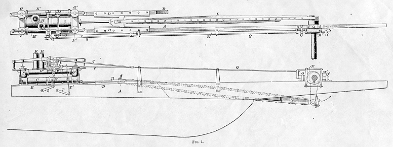
The basic layout of the Western Rivers steamboat engines and paddle wheel is shown in figure 1, above. The cylinder (C) for each engine is horizontal and is set on two heavy wooden cylinder timbers (A & B). On each side of the boat one of the cylinder timbers extends to the pillow blocks supporting the wheel shaft. This is just one early design. There are several variations on the way that the cut-off of the steam to the cylinders is varied, in the way the the valve motion is reversed to reverse the engine, and the motion to actuate the valves may be taken from cams on the wheel shaft or be driven from the middle of the pittman. In this engine, the two cam allow two, fixed cut-offs. One cam allows for a cut-off late in the engine's stroke for maximum power. The second cam allows for cut-off earlier in the stroke for lower steam use and more efficiency when maximum power isn't needed. Note that these are actually cams, not excentrics to allow for a fast opening and closing of the valve. Motion to operate the valves is transmitted by the rods Q, R, q, and r.
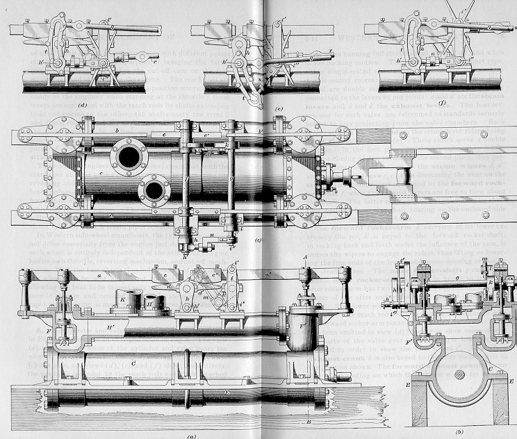
The drawing above is a closer view of the same engine. Note the method of reversing the engine by moving the spider or gab. In (d) and (e) the engine is running forward, in (f) it's running in reverse. When the spider is down it drives pin i", which is connected to shaft g. When the engine is reversed, the spider is raised and pin i' is driven making the motion to shaft g 180 degrees out from that when operating in forward.
Below are several other drawings.

Figure 4 shows the Sweeney valve gear.

Figure 6 shows the assembly which allows cut-off with the California cut-off gear.

Figure 7 is an engine with California cut-off. (This is the variable cut-off design used on the Delta Queen.)

Figure 8 is a drawing of an engine with Rees cut-off.
This is a work in progress. The main source of information is an International Correspondence School text "The Elements of Marine Engineering," Volume II, dated 1900. It includes the fixed cutoff, California (or Cross) cutoff as used on the Delta Queen, and Rees cutoff as used on the Belle of Louisville and W.P. Snyder Jr.
Dick Morris (rmorris@alaska.net).
Anchorage, Alaska
Return to the Alaska Live Steamers home page.
Alaska Live Steamers, Inc.