Don Carveth carvethd@alaska.net.
One of the difficult compromises one is forced to make when designing microcontroller systems is the trade-off between extended memory and I/O points. Using those 18 or so pins for the extended memory bus sure digs into the I/O count, but working with only 2K of memory gets tiring after a while too.
Why not use one of those spare 68HC11 boards you have lying around for additional I/O? Connected as an SPI slave, using a 68HC811E2, you get 8 analog inputs, 11 DI’s, 11 DO’s and a pulse counter, plus an extra serial port! Once the slave is programmed, a few simple master SPI calls retrieve all your data. A very nice black-box project.
Of course, if this was dead easy, we would all have one of these operating by now. The fact is, serial communications projects never seem to be quite as simple as you expect. Additionally, the SPI bus is a little more mysterious to most of us than the familiar SCI. But SPI is really not that complex, its fast, its interruptible and, once you’ve got it working, its very reliable. When I first thought of this idea it seemed like about a three evening venture. Well it really took about three weeks of part time effort, but of course my idea had expanded to add the serial port, which was the most complex part.
This article describes the workings of the device, has source code listings (in Imagecraft C) of the slave unit (SPISlave.c.txt) and a test program for the master (SPITest.c.txt). I have also attached the S19 file for the slave (SPISlave.s19.txt). You can load this up and get all the functionality I have described by just making simple function calls from the master. The physical hook-up is very simple, requiring only the four SPI lines connecting master to slave and an extra line if you want SCI receive capability.
For those of you not too familiar with Motorola’s SPI Bus I’ve included a short description. SPI is included on the 68HC11 and 12 and many other microcontrollers and is becoming more common on other peripheral devices. SPI is a high speed (up to 1 Mbps on the 68HC11) synchronous serial transfer interface intended for in computer data transfer (short distance). This compares to the 9600 bps asynchronous SCI port we’re used to. The HC11 Reference Manual is the best place to learn more about the SPI bus - http://ebus.mot-sps.com/ProdCat/psp/0,1250,68HC811E2~M98635,00.html.
What’s the difference between synchronous and asynchronous? Synchronous data is transferred based on a separate clock signal, specifically the SPI’s SCK line - data is "clocked in". Asynchronous communication does not have this clock – the receiver and transmitter must synchronize themselves as they go – this is what start and stop bits are used for. Because of this, asynchronous communication is really much more complex than synchronous, however that complexity is now built into firmware and largely invisible to the average user. Asynchronous systems also pay a throughput penalty due to this negotiating period, but they do get by with one less control line. Synchronous transfers are immune to interrupts – if the clock stops, the slave can just wait until it starts again and picks up as if nothing happened. Asynchronous transfers can’t handle that.
SPI is rather interesting in that it really ties the two devices together as a virtual 16 bit circular shift register. When the master sends data, 8 bits are shifted into the slave - the slave is shifting 8 bits back to the master at the same time, replacing the contents of the master SPDR register. To initiate an SPI transfer, you simply write a byte to the SPDR register. When done (there is a flag that lets you know) you read SPDR to get the byte returned by the slave. Then you send another byte. You must be sure to delay long enough for the slave to complete the SPI interrupt service routine at the other end. This can be a significant delay, and, without optimizing the ISR, will slow down transfers considerably compared to the theoretical bit rate.
What’s this Master-Slave stuff all about? Well SPI is a master/slave protocol. This means that only one device is allowed to initiate communication (guess who?). The slave can only respond to requests from the master. Master / slave is the simplest network relationship, but, as complexity rises, so do the limitations. In my slave remote, I must use a separate line from the slave to the master to let the master know that the slave has received a character from its SCI port. Multiple devices can be connected to the SPI bus, each with an individual slave select connection to the master, used to select which slave is being addressed at any given time.
The 68HC11 Manual spends considerable time discussing the SPI clock format - CPOL and CPHA (the 68HC12 Manual hardly mentions it). I set both configuration bits to zero without giving it much thought and have never looked back.
The physical connection is very simple:
MASTER |
Connects to |
SLAVE |
Description |
| MOSI | MOSI | Master Out / Slave In | |
| MISO | MISO | Master In / Slave Out | |
| SCK | SCK | Serial Clock | |
| SS | SS | Slave Select | |
| PT2 (any input pin) | PA3 | SCI "Char Recvd" by slave |
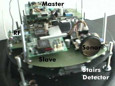
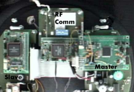
I use my robot as the test bed, although a breadboard would work just fine. The boards are all from Technological Arts. The front board, with the slave, is attached by a 40 conductor ribbon cable to the back board with the 68HC12. The stairs detector, a Sharp GP2D12 with analog output, is located at the front. This works extremely well, rarely giving a false trip and never missing the stairs. Another one, aimed straight ahead is hidden under the top mounting board. This detector, along with the sonar, and a little mathematics, give a continuous distance reading from about 4" to 25 feet. The RF board interfaces between a radio module and the master serial port and screens all the garbage out of the RF. Its working almost well enough to be the subject of another article.
The slave is designed around a 68HC811E2 chip, with 2K EEPROM and 256 bytes of RAM. This is the ideal chip for this but other variants could be used as well.
The slave is executing the following routines in the main loop which runs as fast as possible:
Most of the work is done within these two interrupt service routines:
SCI ISR:
SPI ISR:
The circular buffer concept makes the SCI pass through communications much easier. Rather than always having the first character at the first array location, array pointers to the first character (the next one to be shipped out) and the last character (the last one recieved are kept. When either pointer gets to the end of the array it is reset to 0. The routines simply check if the two pointers are different. If so there must be characters in the buffer and the first pointer is incremented until it equals the last pointer. This method keeps the adding characters activities away from the removing characters activities and ends interaction problems. The only downside is that if you overrun the buffer you lose the whole buffer, not just the overrun characters.
I have kept the functionality of the slave to a minimum but you could have it do some preprocessing of data prior to loading up the Block1 array. The program uses about 1.5 KB, so there is room in the 2K EEPROM for additional features. I have maximized my buffers to use most available RAM, so you may need to cut back on the buffer sizes.
The program is written in Imagecraft C, but by judiciously avoiding the use of pointers (for the most part), I think I’ve made it easily convertible to SBasic or other languages. SBasic does not have a single byte variable comparable to C’s "char" type so it uses twice the buffer room and adds some complexity but should still work fine.
Here are the slave port / pin assignments:
Port / Pin(s) |
Type |
Qua. |
Array Assignment |
| PE 0 - 7 | Analog In | 8 | OutBlock1[0,1,2,3,4,5,6,7] |
| PA 0 - 2 | Digital in | 3 | OutBlock1[8] |
| PA 3 | "Recvd Char" Signal to Master | ||
| PA 4 - 5 | Digital out | 3 | SPIBuff[1] |
| PA 6 | Run LED | ||
| PA 7 | Pulse Accum | 1 | With OutBlock1[8] |
| PB 0 - 7 | Digital out | 8 | SPIBuff[2] |
| PC 0 - 7 | Digital in | 8 | OutBlock[9] |
| PD 0 - 1 | SCI | ||
| PD 2 - 5 | SPI |
My master, in this case, is a 68HC912B32. Now this device has a lot more pins than a 68HC11 so you may wonder why I would need more. Well, a combination of using extended memory (there goes 20 pins), several pins fried by 12 V being plugged into the wrong spot (including my SCI transmit port – ouch) and a general love of tying all sorts of sensors into my robot has left me down to my last few I/O points. Love those Sharp GP2D12 analog I/R distance detectors – one analog input each (these make an excellent "stairs" detector, BTW), and now I have a Dinsmore 1655 electronic compass to try out – two more analogs.
From the masters perspective operation is simple. Three test routines called slvGetPorts, slvSendMessage and slvGetMessage are used to interact with the slave. A separate utility routine called SendSPI looks after loading the SPDR register, resetting the flag and inserting a delay to ensure that the slave has had time to do its work. This delay, incidentally, was determined by decrementing the delay value until problems were noted then adding 25% back on and it is strictly a function of the worst case slave response time. With this delay inserted, a block read of the Port Data (11 bytes) takes place in about 3.5 ms. This is certainly good enough for my purposes but could be improved considerably by optimizing the slave SPI ISR routine by removing unneeded routines and the resulting decision process or by writing critical parts in assembly.
The first SPI character sent lets the slave know what the master is looking for. The slave keeps track of this in variable SPIStatus. If no requests are in progress, SPIStatus = 0.
SlvGetPorts (SPIStatus = 1) gets the slave port data and sends the output data (located in slv_bufout[1] and [2]) at the same time. Slave port A and C values are stored in slvPORTA and slvPORTC respectively. The Port E analogs are located in slv_bufin[1] thru [8]. The print_info function runs every master scan and prints the results of the SlvGetPorts transfer. The slave returns SPIStatus to 0 after a specified number of master requests, so the number of master requests must equal slave BLOCK1_LEN + 2.
The SlvSendMessage (SPIStatus = 2) function runs every master scan and is set up to send a null terminated string. The null is the signal to the slave that the SendMessage mode is complete. The test program sends a string constant but you can send character data from any source - just ensure a null is sent when complete.
SlvGetMessage (SPIStatus = 4) only runs if the "Char Recvd" pin is high, then it keeps requesting bytes until the pin goes low, sending them directly to the master SCI port. These could, alternatively, be assigned to a variable for other uses. This routine could also be set up to run as an ISR instead of polling as I am doing.
Using the master program unmodified, all routines described above are active. The master will output the port data to its SCI port every scan and send a string constant to the slave every scan which should in turn be displayed on the slave terminal. Characters entered on the slave terminal will be echoed on the master terminal.
The master test program is written for a 68HC12, therefore the register names and content will need to be modified slightly for use with a 68HC11.
The program should not be difficult to convert to Sbasic. A few C items you must understand:
Testing is pretty straightforward. Set up a slave 68HC11 with the software installed, connect the pins to the master, with test software loaded, as indicated above and connect some test inputs and outputs. Connect the master to one terminal program on one Com port and the slave to a second instance of the terminal program on a second Com port (or use a second computer as I like to do).
When powered up, the master terminal should display an updating row of decimal values corresponding to the slave port values. The slave terminal should display the built in string sent from the master. Typing on the slave terminal will result in characters showing up on the master terminal, although they do get drowned out in the port data. Turn the port data printout off to see this working better.
Problems can be tricky to figure out as you really can’t see what’s happening between the master and slave. Adding putchar statements directly in the SPI interrupt routines to monitor variables is not practical in the high speed world of SPI. Most problems result from improper array indexing or not properly terminating the mode. I make use of tables that line up the master data with the slave data with the various flag status’ for each byte transferred (take a look in the slave source code). Remember that when a master sends a byte it gets back the slave byte that was set up on the previous request. I also use my oscilloscope to ensure data requests are in fact happening by monitoring the SPI pins.
Hopefully this is enough information to get your slave I/O working. I would be more than happy to answer questions or listen to feedback – just contact me at carvethd@alaska.net. I’ll keep the latest version of the code, and any useful modifications anyone contributes, at my website at http://www.alaska.net/~carvethd/robots/projects/hc11slave/hc11slave.htm.
I could see this device as having other uses with minor modifications. How about an SPI sniffer – forwards all SPI Master Out bus activity to the PC? Just don’t connect the MISO line, connect the SS line to ground (always selected) and make a couple tweaks to the SPI ISR Handler routine. Or it could serve as a PC controlled SPI Master controlling several slave devices.
The software included works as described and has provided the functionality I was looking for. It has not been optimized for speed or reliability. I would not use this software, without further development and testing, for anything critical.
My latest grand plan is to get two 68HC912B32s operating together using SPI to communicate. This project has been a large step towards that goal. Right after I get my Real Time Operating System up and working. Some day I may actually get my robot doing something useful, but I’m having far too much fun on these side distractions to let that detail get in the way.
Don Carveth
Anchorage, Alaska