Power Supply / Frequency Generator
I have long been surviving without a real bench power supply. I’ve used battery packs with rechargeable batteries, but I’ve found myself needing 12 volts and now negative voltage, so I thought it time to build a real supply.
Projects have a funny way of developing. This really started when I was looking for rail-to-rail op amps for my last project, a power meter. I found the beast I wanted from Maxim and ordered a couple samples. While I was ordering those I thought I’d try a couple other items, one of which was a MAX038 High Frequency Waveform Generator. I don’t have a frequency generator and thought this might do the job. When I got the sample and the docs, it was obviously right on the money. The MAX038 will generate sine, square or triangle waves from about 0.1 Hz to 20 MHz, with varying duty cycles. Add a couple adjustable pots and you’re there.
The only problem was that it requires plus and minus 5 VDC referenced to ground. I thought about using a couple battery packs, but finally decided it was time to bite the bullet and build a decent power supply. I found a perfect supply in my junk pile – 5 V at 2 A, 12 V, -12 V, -5 V at 1 amp. I tested it and it worked perfectly. It came as a small box with a terminal strip on one side, including the 120 VAC input. I didn’t see just sitting this thing on the bench the way it was. I need an enclosure.
Then it struck me that the frequency generator and power supply would make a good marriage – after all, they are both supply devices. I found an aluminum case in my junk pile and away I went.
This project is notable as my first attempt at a printed circuit board. That, and using a schematic / circuit board software package added a few wrinkles to the project. I used Eagle software (they supply a freeware demo that is useful for small boards). This works pretty well, except for the parts library. The board came out good but not perfect. A few problems but I can fix those in my next version.
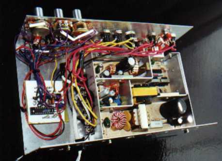
Installing the power supply in the case was pretty straight forward. I decided to add both a 16 VAC RMS output (directly from the supply transformer) and a 2 to 12 VDC adjustable output. I also added a fuse for each supply voltage. Along with an indicator LED and power switch and I was pretty much done. I used banana jacks for each output, all with different colors. For the adjustable output I used a MAX 667, good for 3 to 11.5 VDC at 250 ma, good enough for my CMOS projects.
I constructed the power supply first so that I could prototype the frequency generator. It went together pretty smoothly. I was short a few bits and pieces and, when done, sent an order of f to Jameco for the remaining items.
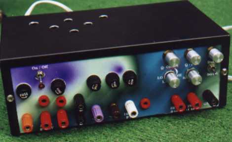
I decided to make a front panel layout on the computer using Corel Draw. This worked very well, although I did manage to set a couple items too close together. I ended up with an accurate drilling template and a psychedelic panel cover sheet that I printed onto Epson Glossy Film, a plastic material. This worked pretty well except that the paint comes off easily and I ended up with a number of scratches. In retrospect I should have put either a clear plastic cover over it or coated it with a thick clear lacquer. Definitely not an HP product.
After I got the supply fired up it was time to prototype the frequency generator. I mounted the parts on a breadboard, and after a few minutes was producing waveforms. Adjusting the frequency, both course and fine, and the duty cycle was simple. I could easily select sine, square or triangle waveforms. The only problem was the output which was a 2 V P-P signal centered on zero. This is OK sometimes, but more often I want a 0 to 5 VDC signal for use with my microcontrollers. I had to add an OP amp to do this level shifting and amplification. Back to the parts bin. The only suitable part I had was a LM358 dual OP amp suitable for +/- 5 Volts supply. It was not rail to rail however, so I would not get to 5 volts. I decided that was still better than my option of gong to +/- 12 VDC supply and the risks that that carries when working with CMOS devices. The MAX038 has a 2.5V reference that helped to establish the bias level. Schematic ????
I thought about adding a voltage and a frequency display but decided those were other projects. I am also short of room in this case. My voltmeter reads frequency and I can use my scope – good enough for my purposes.
Once I finished prototyping, I created a schematic using Eagle. I haven’t yet figured out how to add devices that aren’t on the board or how to add switches and pots. The parts library is pretty clunky – you have to hunt and peck through volumes of parts with non-meaningful names to fine what you want. I therefore set up my off board devices as solder pads. This allowed me to create a board pattern. The autorouter in Eagle works pretty well. You need to tweak your layout, manually route the obvious stuff and then run autoroute until there are no unrouted lines and the pattern looks good.
I used the pattern as a drilling guide, then drew the pattern on the copper by hand with permanent markers, then into the acid for etching. In about 30 minutes I had a pretty good looking board. Some of the thin traces did not take and some of the spots with tight routing were shorting. Fixing the shorts was easier than fixing the missing patterns, so I know how I’ll do the next one.
I installed the components. I found that the .040 hole size was a little large and made soldering difficult. I would use a smaller size drill next time. I installed all of the front panel components - the switches, pots and jacks. I then wired in the power and the panel devices to the circuit board.
Of course, when I fired it up, hardly anything worked. I had to track down a couple shorts on the board and then some logic problems on my selector switches. The pots were wired backward. I found that connecting the power supply ground to the case helped stabilize a wobbly signal. The OP amp wasn’t working due to a wiring short. For some reason Eagle connected a couple OP amps pins I wasn’t using – not sure why.
After that everything worked and I now have a useful addition to my test bench. I haven’t used it for anything useful yet, but now and then I wander by, flip it on along with the scope and watch nice sine waves go by. Very soothing.