Lithium Ion Batteries for Robotics
This article discusses LiIon batteries and describes a universal Lithium Ion battery charger with a Smart Battery interface based on an Atmel ATMEGA8 microcontroller using GCC ver. 3.2
Don Carveth July, 2002 don@botgoodies.com
See www.botgoodies.com for the latest updates to this article.
Rev. 1 - Miscellaneous improvements to c code - see "Notes.txt" for details
Table of Contents
Lithium Ion batteries are becoming a practical alternative for robot power. After my robots sealed lead acid battery passed away recently I started looking for a replacement. I took a quick look on EBay and there was a 10.8V 4500 mAh Lithium Ion laptop battery for $20 that I could not resist. This battery has twice the capacity of my sealed lead acid and was 2/3 the price. I later purchased a Gateway 11.1V 6400 mAH battery for $25. Getting my batteries operational vaulted me into a whole new world which has culminated in the Universal Lithium Ion Battery Charger board described in this article.
These batteries really work very well. My robot seems to run forever without requiring a recharge. Alas, all is not perfect however.
Here's what I now know about Lithium Ion (LiIon) batteries:
The Good
The Not so Good
The biggest issue is the battery charger. There are some chargers available but they match certain batteries which tend to be very expensive. Many laptops have an internal charger and external chargers are not available. Some batteries cannot be charged at all without a charger that is talking to them in the right dialect. Unless you are lucky enough to find a battery with matching charger you need to either build your own or buy a very expensive universal charger.
This article really describes two separate but related technologies: lithium ion battery charging and Smart Battery communications. Either can exist without the other but they are often found together.
The charging parameters are established using one of three methods: if a Smart Battery is detected, the settings from the battery are used. If the "Custom" switch is selected then the settings are set using on-board dip switches and a variable resistor. If not then predefined sets of parameters are selected based on other dip switch positions.
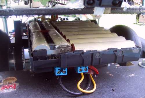
Here is the Gateway LiIon battery mounted in my robot. I removed the case top and the smarts.
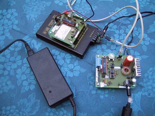
Here is a picture of the complete charging system. That's my temperature transmitter board mounted on the LiIon battery.
Talk to your Battery
Many of the newer battery packs are "Smart". There is an Intel-Duracell spec on this that many battery makers follow. It uses the SMBus (System Management Bus, an I2C derivative) to provide communications between the battery, the charger and a host computer. The battery acts an SMBus master by telling the charge controller what settings to use for charging. The host computer is not required but it can ask the battery for information and be informed of an event, such as charging voltage applied or high temperature. My charger talks to SMBus batteries and allows the battery to set the charge parameters. When I refer to "Smart Battery" from here on I mean the SMBus system, "smart" refers to smart batteries in general.
Unfortunately, not all batteries speak the same language. Most of the modern batteries are smart but few advertise what protocol they use. Some batteries will only charge if they are talking to a charger speaking the right dialect. I was lucky enough to get one that said "Smart Battery" right on it. My second battery (Gateway 11.1V 6400 mAH) uses a protocol I never did figure out. I found a Gateway charger for a similar battery but it would not converse with my battery.
Here is a good site for Smart Battery info.
LiIon Battery Characteristics
A Li-Ion cell produces a nominal 3.6 or 3.7 volts per cell. Operating voltage is really 4.2V down to 3.7V after which they decline rapidly. Cells are combined to produce higher voltages so common voltage ratings are 3.6, 7.2, 10.8 and 14.4 volts (or 3.7, 7.4, 11.1 and 14.8 volts). Cells are wired in parallel to increase battery capacity. The asking prices are pretty much a function of the popularity of the laptop they are associated with. The first one I bought was for a no-name brand, thus a low price. The battery lists for about $160 new.
The batteries usually include a number of safety devices such as varactors that act as resetable fuses, thermistors that monitor battery temperature and report back to the charger, over voltage monitoring, etc. The minimum features should be a varactor and thermistor. I finally had to strip the smarts out of the Gateway battery to get it operational but I installed a 2A varactor and a 10K nominal thermistor that can be monitored by my charger for protection.
The battery parameters that you need to know to charge safely are:
This information is sometimes written on the battery case but usually is not. Web searches usually don't reveal the information either as batteries are normally tied to specific laptop model numbers and even basic parameters like nominal voltage and capacity are not often not shown. You need to know how to determine these numbers yourself.
Numbers of cells is determined by dividing the battery nominal voltage by 3.7. Maximum charge voltage is usually 4.2 volts per cell. If you are unsure use the safer 4.1 volts. Maximum charge capacity is normally close to 1C but can be as low as 0.5C. Use 0.5C if you have no other information. Battery pin-out can be tricky. My Gateway has no pin markings at all. Battery plus and minus were not even obvious as it required that two pins be shorted before it would even work. The thermistor can be found as a resistance to ground. The Gateway battery is 10K, the other one is 300 ohms. The remaining pins are likely used for comm but be careful. Test the pins for activity after it is power up. You could have 12 volts appear on a pin and damage your uC input. I have added an input resistor and 5.1V zener to my two comm inputs for protection against this.
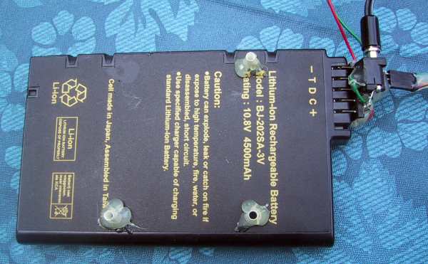
Check this article out for more info on the batteries themselves. Here's a picture of my first battery.
My robot operates at just under 1 amp when it's running around. Theoretically it should run for over four hours between charges - and it does. In addition, the Li-Ion battery is 10% smaller in volume than and about 3/4 the weight of my old 12V 2300 mAh sealed lead acid battery.
Charging
Charging the batteries takes some control or the batteries will be damaged or could even explode. I was not able to find the specifications for my battery (a major plus for the smart battery concept), therefore I had to make educated guesses based on units with similar model numbers and parameters.
The most common specifications call for charging currents between 0.5C and 1C where C is the nominal battery capacity expressed in mAh's. Some specs indicated charging rates of 2C would be acceptable. Higher charge rates resulted in somewhat reduced capacity (15% for 2C vs. 1C). Overcharging can hurt the battery and could cause it to blow up. On the larger batteries such as the 6400 mAH the charger capacity normally will limit this anyway. Barring any other information I would say 0.5C would be a safe value.
Charging generally follows these steps:
Using this program and charging at 1C should fully charge a battery in 2-1/2 hours.
Literature on the batteries is rather spotty. I learned enough to believe Li-Ion would work for me. The only thing I needed to do was find or build a charger. My first battery turned out to be from an AMS Tech Rodeo 7000 laptop - they sell an external charger for about $200. I searched Ebay and the Electronics supply houses for generic smart chargers but I could not find one that would handle my battery. There are chargers for under 1A around, but not for the big guys. I decided I would have to build one.
I considered four possible ways to build such a charge controller:
My first attempt at this was based on the MAX745 from Maxim, a non-smart switching mode device. One problem with these chips is that they are available in surface mount only - they are designed to go in cell phones and laptops remember. The other problem was, that despite much trying, I was never able to get a charger working properly. I finally got one to the "sort-of-works" point but it still took some hand waving and nose pointing to get it started sometimes.
Atmel then published App Note AVR450 describing how build a universal charger for Ni-Cads, NiMH, SLA and LiIon batteries based on a AT90S4433 microcontroller. This seemed to be the answer and is what I used as the basis of this design. I modified it considerably, added the Smart Battery interface (which necessitated upgrading from an AT90S4433 to an ATMEGA8) and added preset and adjustable battery parameters. I substituted available transistor, MOSFET, Schottky diodes and coils for those specified and it all worked pretty much from the get go.
The article now describes how to build a charger controller board and how to program the AVR microcontroller. You should have a LiIon battery you can practice on - my practice battery is still alive and well despite considerable abuse. The more you know about the battery the better: Maximum charge voltage and amps (sometimes printed on the case), thermistor (yes/no and resistance - they are not always 10K) and Smart Battery or not.
In addition to the charge controller a DC supply capable of providing at least 2 volts more than the max cell voltage (14.6 volts in my case) at the desired current is required. At the capacities I want you are out of the "Wall wart" category. I found a laptop supply for a Dell rated at 18V @3.5A.
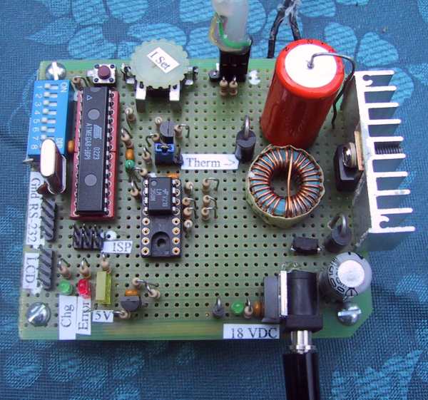
The board is fabricated using easily obtainable components - refer to the parts list in the Atmel App Note. I made some substitutions and marked the schematic up accordingly.
The ATMEGA8 is a new release and has 8K Flash, 1K RAM in a 28 pin narrow DIP package and can be clocked up to 16MHz. If you are willing to eliminate the Smart Battery interface and delete some of the debug code the code could be made to fit in an AT90S4433 as per the original Atmel design.
The microcontroller software used is GCC version 3.2. This version is required to accommodate the direct I/O assignments that resulted from the conversion from IAR that was used in Atmels App note. The software is actually a combination of Atmels, converted from IAR, an I2C interface, converted from 68HC11/Imagecraft and my own GCC code. As a result the program does not read as well as I am used to as 3 different styles are evident.
The current / voltage control is managed by a PWM output into a P-Channel MOSFET. A large inductor / capacitor combination is used to stabilize the circuit. The special purpose chargers generally run at much higher frequencies ( 150KHz compared to 15KHz) and can thus use smaller components, not that important in my case.
The charger provides a continuous data stream output from the UART for your PC. I send initialization info and continuous charge status information from the charger, and, if a Smart Battery is connected, the battery, that can be viewed on a PC terminal program. Baud rate is set at 115K but could be lowered as desired.
The charge LED flashes quickly during constant current mode, slower during constant voltage mode and ends up at steady on when charging has completed.
The charger was operational after a weeks part time effort, another few days were spent on the Smart Battery interface and a couple more to document the whole thing.
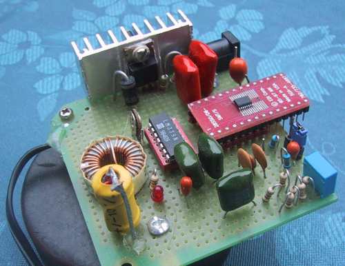
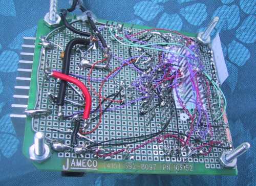
For one-off projects such as this I prefer to use wire-wrap in combination with soldering. I use a foil grid one side board with foil down. I spot solder most components to the grid and use wire-wrap to wire it up. This board had a requirement for larger power wire which was installed where needed. Notice from the photo that I use homemade wirewrap pin labels - I print them on the printer and push them down over the pins. Works quite well. I also print out top of board ID labels. This project would be a good candidate for a printed circuit board - I just don't have any incentive now that my board is working.
There are three attached schematics that describe the board. First is the microcontroller itself, then the Atmel designed charge control circuitry and finally the Atmel designed reference voltage circuit.
The microcontroller physical design is pretty much a standard AVR design. A 7.3 MHz crystal is used (the ATMEGA8 can take up to 16 MHz). I added an 8 point dip switch for battery parameter selection and a variable resistor for setting Charge current in "Custom" mode. I include a UART interface but did not install the RS-232 interface on the board as I have a very useful cable with a MAX233 built in.
You can see from the photo that I have attached a heat sink to the HexFET. I suspect I could get up to 3.5 to 4 amps without problems with this setup. So far I've held back to 2.5 amps as I have no spare HexFETs in house and don't feel like doing destructive testing. Read the App note for a good description of how this circuit works. I mounted the power components on the opposite end of the board from the uC and kept three separate grounds (uC, analog, charger power) connected only at a single point. The op amp circuit used to measure battery voltage and current will take a little fiddling around. You do not need to have exact values as the circuit can be calibrated using software. Refer to the App Note for determining your specific resistor and calculating the inductor size. Here is an Excel calculation worksheet.
In case you are unable to get the thermistor operational I have a provision to jumper in a 10K resistor and bypass the protection. Obviously this should be a last resort. I may need to install several jumper selectable thermistor inputs as there seems to be a wide range of resistance ranges in use.
I use a standard power jack for the power supply connection and at the battery. In addition I have a separate 3 circuit cable to connect to the thermistor and Smart Battery lines at the battery. The actual battery connectors are very specific and not easy to find. I found one for my first battery but not for the Gateway. You will likely have to fab something up yourself.
You will require the latest (as of July, 2002) version of GCC, version 3.2 as provided on the AVRFreaks GCC web page, to be able to program the ATMEGA8 and take advantage of direct I/O register assignment mode which is new in this release.
Here is the set of c code files. Take a look at the "notes.txt" file. It describes the IAR to GCC conversion, the mods made to Atmels software, uC resources used, pin assignments and general notes about the software.
The main file is BC.c. Program flow starts with setup then moves directly into the LiIon fast charge algorithm in LiIon.c. It is here that the program checks for the existence of a Smart Battery. If detected charger settings are based on the information received from the battery, if not, settings are based on the on-board dip switch settings.
The charger then checks for over/under battery temperature and over voltage and flags an error if any of these are detected, sending a short error message to the PC. If OK control proceeds to the Constant Current loop where the PWM signal on-time is adjusted up or down until the measured current matches the specified fast charge current. The charge LED flashes quickly during this mode. When the Maximum Charge Voltage setting is reached then the mode switches to Constant Voltage and a new loop is entered that uses the same method as above to control voltage at the Maximum Charge Voltage point. The LED now flashes more slowly. This continues until 30 minutes after the charge current, which is decreasing with time in constant voltage mode, reaches the minimum (set at 50 mA per 1600 mAH of capacity). The charger then shuts off and the LED goes on steady.
The Atmel software included a trickle charging algorithm that I left intact but commented out. I don't see myself using it. I also removed most references to alternate battery chemistries. The program was designed to have the charge settings, specified in the BC_defs.h file, defined at compile time. I converted all of these settings to variables which are defined in various ways as described above. I deleted the BC_defs.h file and consolidated the user setup area in LiIon.h. Be sure to review this file and update important parameters such as Maximum Charger Current before firing things up. The preset settings (pick up to 8 different batteries) are set near the end of the LiIon.c file.
The voltage, current and temperature analogs must be calibrated. I used my calculation sheet to determine nominal resistor values, as described in the App Note, then fine tuned them by setting the VOLTAGE_STEP and CURRENT_STEP. This gives the number of mV or mA per each of the 1024 steps of the 10 bit A/D input. The thermistor values never leave the raw state though I see an NTC look-up table which was never implemented by Atmel.
The Smart Battery routines, located in sbcomm.c, are based on bit-banged I2C 68HC11/Imagecraft software. I converted them to AVR/GCC and added information and functions specific to the Smart Battery spec. Take a look at SBComm.h for the available SB commands. The ATMEGA8 has a built in I2C port but I did not use it. These routines could be extracted and used separately from the charger if desired, say, to monitor battery status of your robot during use. It provides some useful information such as voltage, amps, time remaining until recharge required (based on current usage rate), percent capacity, temperature, status flags, etc.
Also worth discussing are my StdDefs files. I have included in StdDefs.c routines that I seem to use in almost all programs such as putchar, putBCD, putstr, run_led, msleep, etc. StdDefs.h includes defines that simplifies changing uC models and crystal frequencies, primarily with respect to the UART, and has some other standard macros that I frequently use.
I removed the Atmel debug statements and used my own putchar / putstr / putBCD routines instead. All errors will report a string back to the PC. The error handling system has not been well tested - To date everything has worked and I haven't needed it.
Once wired up and with the software installed you should be ready to go. I like to have my scope on during this phase to watch the PWM signal and check for data on the SMBus. The PC was connected to the UART and running HyperTerminal. I started off using load resistors instead of the battery just in case. I found a couple 7.5 ohm 25 watt resistors that were ideal. I then calibrated my voltage and current measurement by adjusting VOLTAGE_STEP and CURRENT_STEP until the readings reported on the PC agreed with my voltmeter measurements. You need to be sure your meter is pretty accurate as the maximum charge voltage needs to be accurately maintained to ensure the battery takes its full charge.
By changing LiIon_CELL_VOLTAGE and CAPACITY I was able to force the charger into both operating modes. The PWM circuit worked right from the start which was a relief after the struggles I had had with the MAX745 circuit. Once I was confident that the PWM worked and the charging routines were working I connected the battery power. The PC feedback looked good and the voltage was slowly rising in Constant Current mode. I then connected the Thermistor / Smart battery connector and troubleshot those two functions.
Note that the software is set up as a single pass. The uC must be reset to restart the sequence or to accept new charge settings from either the Smart Battery or the dip switches.
If a Smart Battery is connected then there is nothing to do but plug in the battery, then plug in the power and let it charge. If not you need to select the correct charge settings for your particular battery. In custom mode you use on board dip switches and the variable resistor to set CELLS, LiIon_CELL_VOLTAGE and CAPACITY (same as max charge current). If the "Custom" dip switch is not selected then the software goes to the GetBatteryData() function where it selects a predefined set of parameters based on the PreDef0, 1 and 2 switch settings. You can define up to 8 different batteries in the GetBatteryData() routine.
NB!!!! You must be very careful at this point not to select a battery with higher current or voltage settings than the battery you have connected. I would recommend monitoring voltage and current via the PC or with a volt-ammeter to be sure. My Smart Battery reports back a Max Charge Current of 0 if the voltage is above the max charge voltage.
The article assumes you are familiar with basic operation and programming of an AVR microcontroller. If not, a visit to AVRFreaks.com is in order. The AVR is a very straightforward uC to learn. If you use the c language then you will enjoy using GCC which is powerful, easy to set up and free. You can have a complete development environment set up for the cost of a micro and a few support parts and an AVR-ISP programmer which is about $35.
You can see there are some risks associated with charging LiIon batteries. I would not attempt to construct this charger if you do not have the skills necessary to safely build, program and test it. Even then care is required when switching between batteries. Using the charger for a specific battery only is the safest method.
Good luck with your project and contact Don Carveth, don@botgoodies.com if you have any questions or comments.